–
Introduction
–
An electric heating strip provides supplementary or primary warmth in HVAC air handlers and package terminal air conditioner units. Reading a heat strip wiring diagram correctly ensures proper installation, prevents equipment damage, and maintains compliance with regional electrical codes. These schematics map the flow of high-voltage supply current alongside low-voltage control signals from a climate controller or thermostat wiring array. Technicians and DIY installers rely on these technical schematics to identify terminal designations, relay coil connections, and thermal limit safety switches.
💡 Technical Key Takeaways:
- Core Focus: Diagnostic schematic and terminal connection layout for Heat Strip Wiring Diagram.
- Target Scope: Field technicians, automotive DIYers, and residential/commercial electricians.
- Safety Rule: Always disconnect the primary power source/battery terminal and verify zero voltage with a multimeter before touching wires.
–
Core Concepts and Wiring Fundamentals
–
Supplemental resistance heat systems combine high-amperage 240V or 208V AC circuits with 24V AC control logic. Power enters the air handler through dedicated circuit breakers or disconnects, routing directly to sequencer relays or magnetic contactors. When the control system calls for heat, a low-voltage circuit energizes the relay coil, closing heavy-duty contacts that feed current to the resistive heating elements.
–
Sizing conductors correctly is critical because resistance heaters draw substantial continuous current. Copper wire gauge must match the exact ampacity rating specified on the equipment data plate. Regional standards, such as the National Electrical Code in the US, the Canadian Electrical Code, BS 7671 in the UK, or AS/NZS 3000 in Australia, dictate minimum conductor sizing, overcurrent protection limits, and disconnect placement requirements for fixed heating equipment.
–
Proper overcurrent protection and conductor sizing are mandatory for fixed electric space heating equipment to prevent dangerous thermal overload and structural degradation of wiring insulation — NFPA 70 National Electrical Code
–
Diagram Explanation and Key Components
–
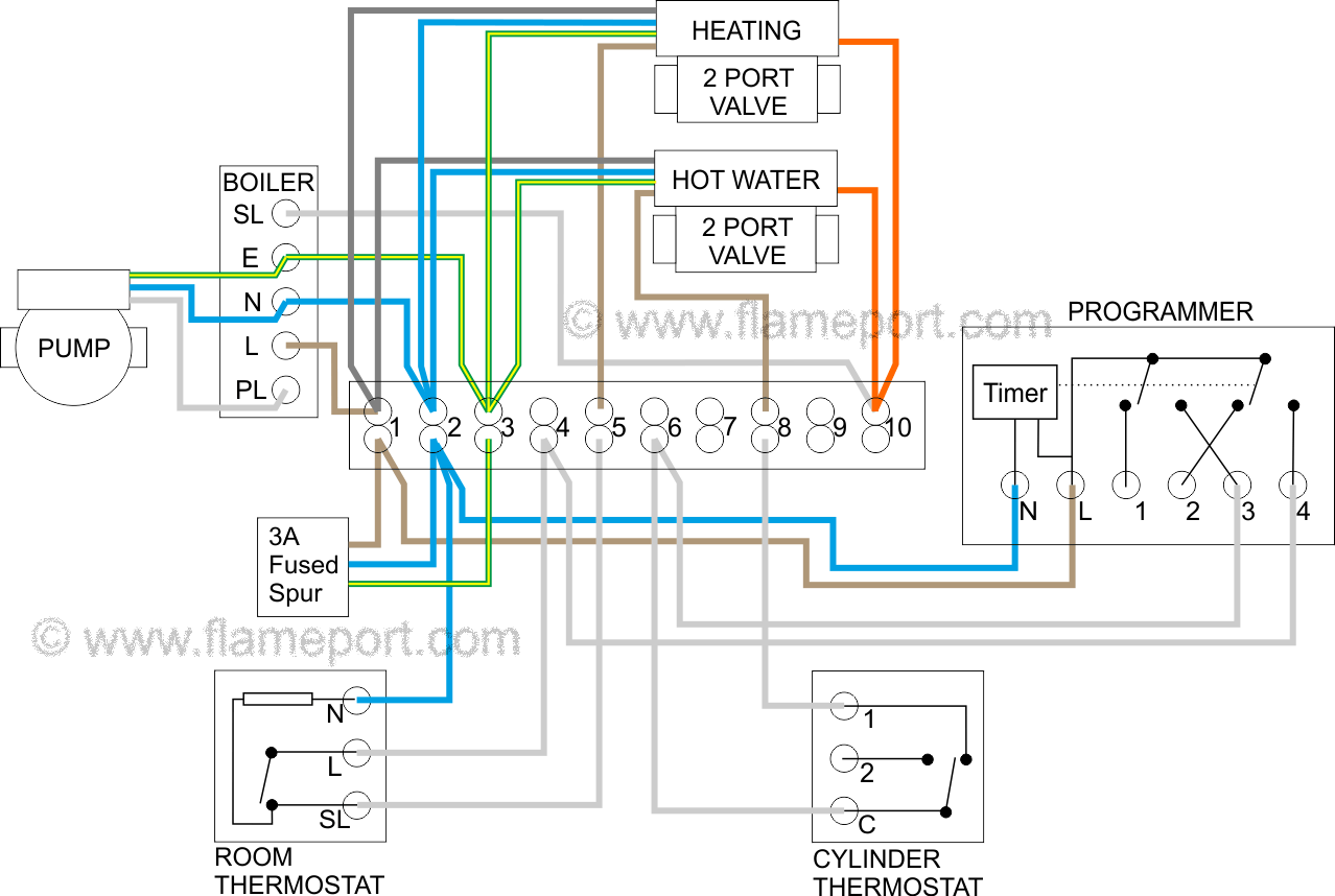
Factory schematics use standardized graphical symbols to represent electrical components. Heating elements appear as jagged resistance lines, while thermal cutouts and limit switches display temperature-activated switch contacts. Relays and sequencers show a distinct coil symbol paired with normally open or normally closed contact blades. Master symbols and abbreviations vary slightly between manufacturers, making a thorough review of the schematic legend essential before testing begins.
–
Color codes on residential HVAC equipment typically follow standard conventions, though variations exist across international markets. Black and red conductors usually carry high-voltage line power, while white or blue serves as a neutral where applicable. Low-voltage control circuits utilize color-coded conductors like red for 24V power, white for heating control, and green or yellow for fan operation, which closely aligns with principles found in Home Electrical Wiring practices.
–
Common Problems and Troubleshooting Methods
–
System failures often manifest as a complete lack of heat, intermittent warming, or tripped household breakers. Diagnostic procedures begin at the power source. Technicians must de-energize the equipment and verify zero energy state using a calibrated multimeter before inspecting internal components. Visual inspection frequently reveals loose terminal screws, pitted relay contacts, or burnt wire insulation caused by high resistance connections.
–
Testing continuity across thermal limit switches helps isolate open-circuit faults. If a high-limit switch trips repeatedly, airflow restriction, a failing blower motor, or an incorrectly staged sequencer is usually the root cause. Technicians must treat symptom-based troubleshooting as a diagnostic process rather than a guarantee of immediate repair, ensuring that underlying airflow or control issues are fully resolved before replacing expensive components.
–
Practical Tips and Safety Considerations
–
Working with residential heating circuits carries severe electrical shock and arc flash hazards. Always isolate power at the main service panel and test with a reliable voltage detector before touching internal terminals. Main power wiring requires high-temperature insulation, such as THHN or equivalent regional ratings, because resistance heaters generate intense ambient heat within the air handler cabinet.
–
A frequent installation error involves mismatching sequencer timing or jumpering high-voltage stages incorrectly, which leads to immediate overcurrent tripping. Ensuring proper torque on all mechanical screw terminals prevents localized overheating and arcing. For complex installations or where local law dictates, consulting a licensed professional ensures full adherence to applicable Safety NEC NFPA guidelines or local regulatory frameworks.
–
Conclusion
–
Mastering the interpretation of an electric resistance heating schematic empowers technicians and skilled DIYers to service climate control equipment safely and efficiently. Understanding the interplay between high-voltage heating loads and low-voltage control logic prevents costly misdiagnoses and dangerous installation errors. Proper preparation, strict adherence to safety protocols, and careful reference to the manufacturer Wiring Diagram remain the foundation of successful electrical troubleshooting.
Quick Wiring Specifications & Terminal Guide
| Component / Circuit | Standard Wire Gauge | Recommended Protection |
|---|---|---|
| Control & Trigger Signals | 18 – 20 AWG | 5A – 7.5A Inline Fuse |
| Standard Auxiliary Load | 14 – 16 AWG | 15A – 20A Circuit Breaker |
| Main Power Feed / Supply | 10 – 12 AWG | 30A – 40A Heavy-Duty Relay |
Images References

–
–

–

–

–