–
Introduction
–
An irrigation pump wiring diagram serves as the definitive roadmap for installing, maintaining, and repairing agricultural and residential water delivery systems. These schematics outline the physical and electrical pathways connecting power sources, control boxes, pressure switches, and the pump motor itself. Mastery of this document ensures that pumps operate efficiently without risking catastrophic motor burnout or electrical hazards. Proper interpretation of these layouts directly impacts installation quality, preventing costly downtime during peak growing or landscaping seasons.
💡 Technical Key Takeaways:
- Core Focus: Diagnostic schematic and terminal connection layout for Irrigation Pump Wiring Diagram.
- Target Scope: Field technicians, automotive DIYers, and residential/commercial electricians.
- Safety Rule: Always disconnect the primary power source/battery terminal and verify zero voltage with a multimeter before touching wires.
–
–
Agricultural and residential irrigation systems typically rely on single-phase or three-phase mains voltage, demanding strict adherence to safety protocols and regional electrical codes. Whether referencing the NEC in the United States, CEC in Canada, BS 7671 in the United Kingdom, or AS/NZS 3000 in Australia, understanding schematic conventions prevents dangerous miswiring. Correctly reading a Wiring Diagram allows technicians to trace faults methodically rather than relying on guesswork, ensuring long-term reliability in wet outdoor environments.
–
Core Concepts and Wiring Fundamentals
–
Irrigation pump circuits generally fall into two categories: low-voltage control circuits (typically 24V AC from an irrigation controller) and high-voltage power circuits (120V, 240V, or higher AC mains). The low-voltage side commands automated valves and relay coils, while the high-voltage side delivers heavy current directly to the pump motor windings. Separation of these voltages is vital for protecting sensitive timing devices from high-voltage surges.
–
Power delivery relies heavily on correctly sized conductors, thermal overload protection, and reliable grounding. Deep-well submersible pumps require specialized waterproof splices and control boxes containing capacitors and start relays. Centrifugal surface pumps, conversely, sit above ground and usually utilize simpler terminal blocks inside the motor housing. Every connection point represents a potential resistance source, making weather-resistant junctions and proper Wire Color Gauge Code compliance essential for preventing voltage drop over long trench runs.
–
[Standard Practice] — National Electrical Code (NEC) / NFPA 70 guidelines require proper grounding and overcurrent protection for all outdoor motor installations to mitigate shock hazards in damp environments.
–
Diagram Explanation and Key Components
–
Schematics for water delivery systems utilize standardized symbols to represent physical hardware. Motor windings, centrifugal switches, pressure switches, float switches, and electromagnetic contactors each possess distinct graphical representations. A standard layout generally splits into two sections: the control logic diagram and the power distribution diagram. Cross-referencing these sections helps technicians understand how a signal from a remote sensor ultimately closes a heavy-duty contactor to energize the pump.
–
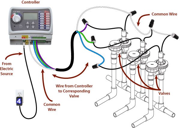
Color coding varies significantly by region and application. In North America, 120V/240V residential lines typically use black and red for hot conductors, white for neutral, and bare copper or green for ground. In the UK and Australia, harmonized standards dictate brown for live, blue for neutral, and green-and-yellow for earth. Low-voltage multi-strand cables running from controllers to valves use distinct color combinations per zone, which must be meticulously documented during installation to prevent diagnostic confusion later.
–
Common Problems and Troubleshooting Methods
–
Field diagnostics often reveal recurring failure points in outdoor water systems. Submersible pumps frequently suffer from lightning-induced voltage surges, failing start capacitors, or compromised drop cable splices caused by moisture intrusion. Surface pumps generally exhibit issues related to mechanical seal leaks leading to motor bearing failure, or pressure switch contacts pitting and failing to close the circuit.
–
A systematic diagnostic approach begins by verifying input voltage at the disconnect box using a calibrated digital multimeter. Technicians must de-energize the system and verify zero energy states before performing continuity checks on motor windings or inspecting relay contacts. When mains-voltage work is required, ensure power is fully isolated and verified with a trusted tester. Always use a licensed electrician where local law mandates professional installation for permanent wiring.
–
Practical Tips and Safety Considerations
–
Successful installation demands high-grade materials rated for outdoor or direct-burial use. Standard indoor building wire degrades rapidly when exposed to moisture and soil acids; UF-B cable or individual THWN conductors inside schedule 80 PVC conduit are standard requirements depending on local code. Waterproof gel-filled wire connectors are mandatory for low-voltage splices inside valve boxes to prevent corrosion.
–
A common mistake in the field involves undersizing wire gauge for long runs from the main service panel to a remote pump house. Voltage drop causes excessive motor heating, reduced torque, and premature failure. Referencing proper sizing charts ensures the pump receives adequate running current under full load. Integrating robust lightning arrestors and dedicated equipment grounding rods near the pump location provides an essential layer of defense against seasonal storms.
–
Conclusion
–
Interpreting an irrigation pump wiring diagram bridges the gap between theoretical electrical knowledge and reliable physical installation. Respecting voltage boundaries, adhering to regional standards, and utilizing methodical diagnostic procedures safeguard both equipment and personnel. For broader electrical concepts and related system layouts, explore additional technical resources such as Home Electrical Wiring.
Quick Wiring Specifications & Terminal Guide
| Component / Circuit | Standard Wire Gauge | Recommended Protection |
|---|---|---|
| Control & Trigger Signals | 18 – 20 AWG | 5A – 7.5A Inline Fuse |
| Standard Auxiliary Load | 14 – 16 AWG | 15A – 20A Circuit Breaker |
| Main Power Feed / Supply | 10 – 12 AWG | 30A – 40A Heavy-Duty Relay |
Images References

–

–

–

–

–
–