–
Introduction
–
The 9 lead 3 phase motor wiring diagram is an essential blueprint for connecting dual-voltage induction motors found across industrial, commercial, and heavy-duty residential setups. Mastering this configuration allows technicians to adapt a single motor to either low or high supply voltages—typically operating on standard industrial distribution grids. Understanding how these nine leads interlock prevents catastrophic phase-to-phase shorts, protects equipment from thermal overload, and ensures reliable torque delivery. Safe handling of these circuits aligns with standards set by the National Electrical Code (NEC/NFPA 70) in the United States, the Canadian Electrical Code (CEC), BS 7671 in the United Kingdom, and AS/NZS 3000 in Australia.
💡 Technical Key Takeaways:
- Core Focus: Diagnostic schematic and terminal connection layout for 9 Lead 3 Phase Motor Wiring Diagram.
- Target Scope: Field technicians, automotive DIYers, and residential/commercial electricians.
- Safety Rule: Always disconnect the primary power source/battery terminal and verify zero voltage with a multimeter before touching wires.
–
Core Concepts and Wiring Fundamentals
–
A standard 9-lead dual-voltage motor consists of six individual stator winding groups inside the housing. Manufacturers bring out nine distinct leads to allow these coils to be configured in either a series connection for high voltage or a parallel connection for low voltage. The windings are designated numerically from 1 through 9. Recognizing how these coils interact requires familiarity with standard Symbols Schematics to interpret terminal markings correctly before applying power.
–
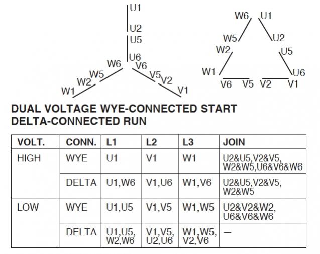
In a wye-configured (star) dual-voltage motor, leads 1 through 3 serve as the primary line terminals, while leads 4 through 9 form the internal connection points and branches. Depending on whether the installation requires 230V or 460V (in North American systems) or corresponding international voltages, the physical jumper configuration changes completely. Applying a low-voltage parallel setup to a high-voltage supply will immediately draw excessive current, tripping protective devices or burning out the varnish insulation on the copper magnet wire.
–
[Finding] — According to the National Fire Protection Association (NFPA), electrical distribution and lighting equipment failures remain a leading factor in industrial and commercial electrical fires, underscoring the necessity of precise terminal torque and correct wire sizing.
–
Diagram Explanation and Key Components
–
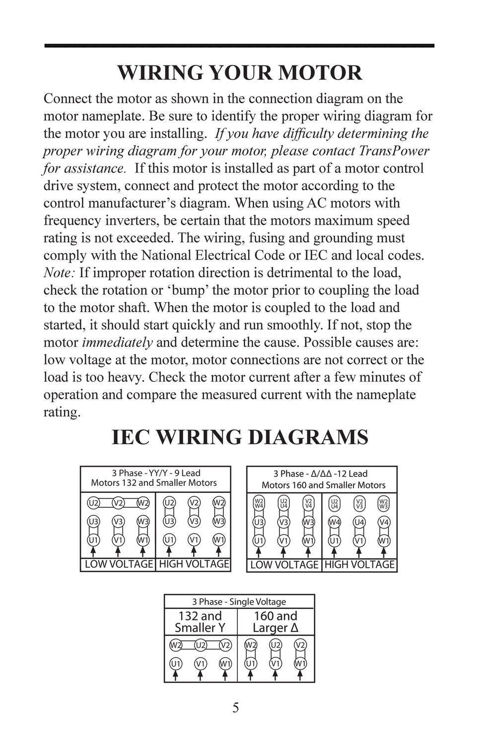
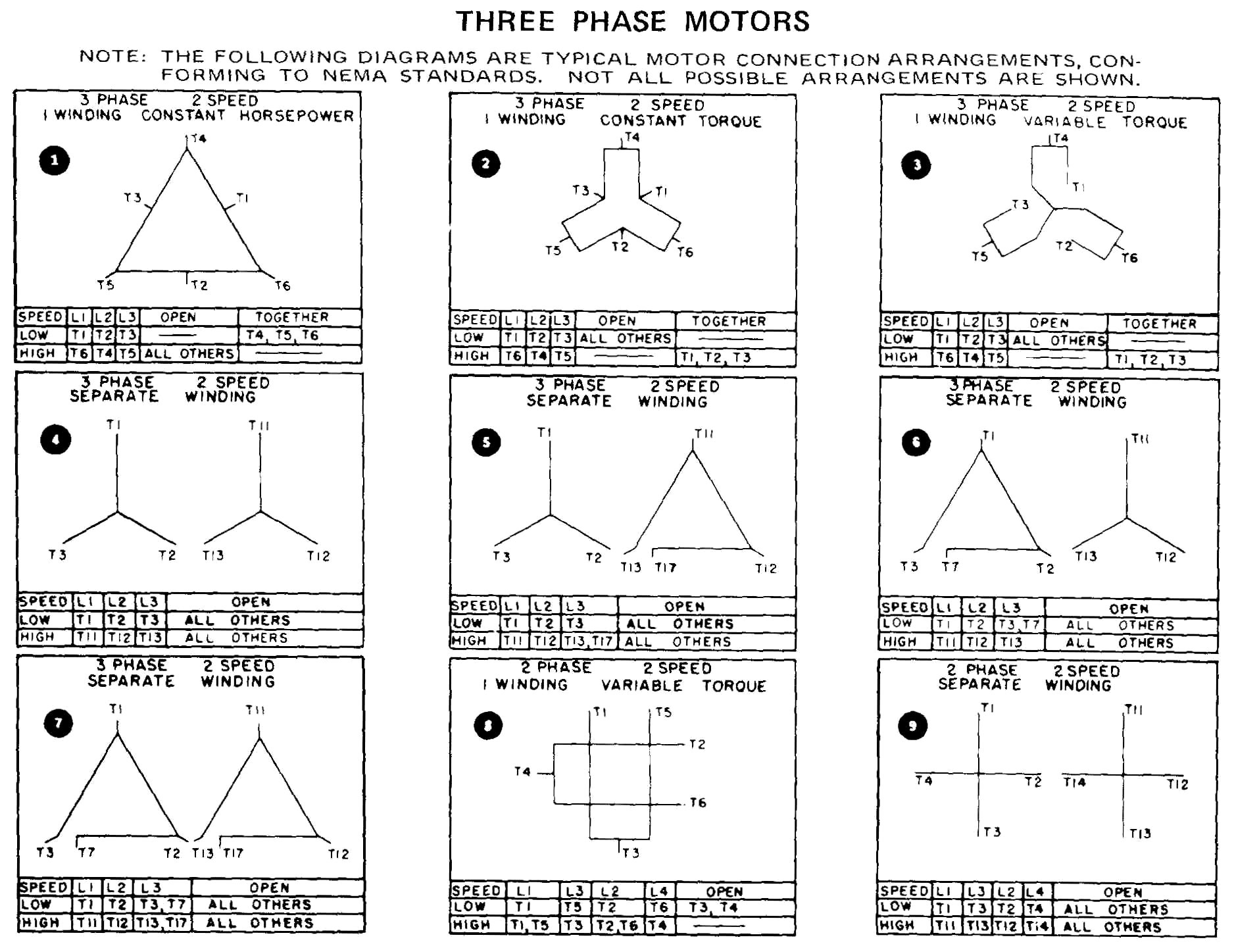
Reading a 9-lead motor connection schematic involves identifying the dual-voltage groupings. For low-voltage operation (such as 230V), leads 1 and 7 are tied together with Line 1; leads 2 and 8 with Line 2; and leads 3 and 9 with Line 3. Simultaneously, leads 4, 5, and 6 are twisted and capped together to form a neutral center point. For high-voltage operation (such as 460V), Line 1 connects exclusively to lead 1, Line 2 connects to lead 2, and Line 3 connects to lead 3. The remaining leads pair up: 4 and 7, 5 and 8, and 6 and 9, while leads not tied to lines are securely isolated.
–
Color coding of supply conductors varies significantly by region. In the United States and Canada, 3-phase commercial systems often use black, red, and blue (or brown, orange, and yellow for 480V) for ungrounded phase conductors. In the UK and Europe under BS 7671, phase colors follow brown, black, and grey. Australia and New Zealand adhere to red, white, and blue (or brown, black, and grey under harmonized standards) for active lines. Cross-referencing local Wire Color Gauge Code standards ensures compliance and safety.
–
Common Problems and Troubleshooting Methods
–
Motor installation errors usually manifest as a tripped breaker, a humming motor that fails to rotate, or severe overheating on a single phase. A common mistake in the field involves misidentifying lead numbers due to faded factory stampings or solvent wash-off during maintenance. Technicians should never guess lead identities; instead, continuity testing with a digital multimeter is required to map winding groups before making final splices.
–
Diagnosis begins by de-energizing the circuit, locking out the disconnect switch, and verifying a zero-voltage state with a calibrated meter. Next, check for an open winding by measuring resistance across pairs (1-4, 2-5, 3-6, etc.), which should show balanced, low-ohm readings. Insulation breakdown to ground requires an insulation resistance tester (megohmmeter) to verify that the stator windings have not degraded from moisture or chemical exposure. Frame grounding must always be verified to prevent shock hazards.
–
Practical Tips and Safety Considerations
–
Mains-voltage work carries severe arc flash and electrocution risks. Always de-energize the circuit upstream and verify zero energy with a trusted voltage tester before touching any terminal blocks. Qualified personnel must perform installations where local law dictates. Mechanical connections inside the terminal box demand proper torque using calibrated tools; loose wire nuts or split bolts create high-resistance joints that generate destructive heat under load.
–
Proper physical protection of the motor leads prevents vibration fatigue where conduit meets the connection box. Using liquid-tight flexible metallic conduit with appropriate fittings keeps oil, coolant, and moisture away from the splices. For deeper insight into regulatory compliance and hazard mitigation, review documentation available through Safety NEC NFPA guidelines.
–
Conclusion
–
Proper execution of a 9 lead 3 phase motor wiring diagram bridges theoretical electrical principles and reliable industrial machinery performance. Verifying lead numbers, matching regional voltage requirements, and maintaining tight, insulated connections prevent premature equipment failure and costly downtime. Careful diagnosis and adherence to established electrical safety standards protect both the technician and the electrical infrastructure.
Quick Wiring Specifications & Terminal Guide
| Component / Circuit | Standard Wire Gauge | Recommended Protection |
|---|---|---|
| Control & Trigger Signals | 18 – 20 AWG | 5A – 7.5A Inline Fuse |
| Standard Auxiliary Load | 14 – 16 AWG | 15A – 20A Circuit Breaker |
| Main Power Feed / Supply | 10 – 12 AWG | 30A – 40A Heavy-Duty Relay |
Images References

–

–

–

–

–
–